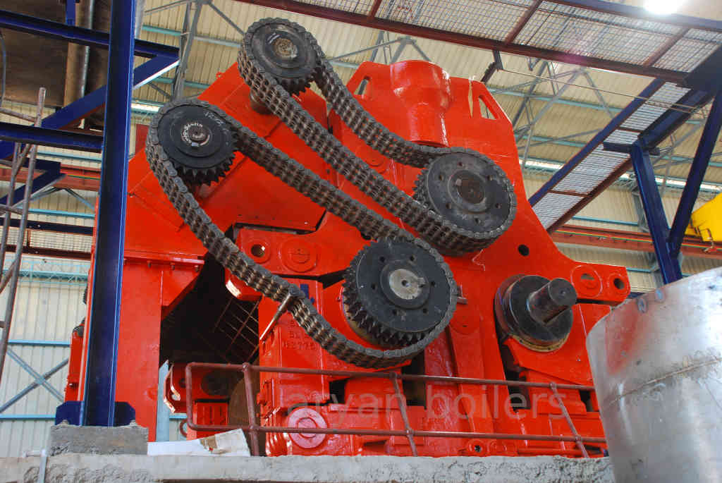
Sugar Cane Mills suitable for 10,000 TCD
Sugar Cane Mills
Salient Features Of Aryan Boiler Mills
- Anti-friction bearings for all carrier shafts reduce wear & tear of shafts which in turn reduces the power consumption.
- The top of the cane carrier will be fully covered (except in the horizontal part) with mild steel plates and adequately braced with angle iron sections. This reduces the flying of prepared cane dust in the surroundings and also provides rigidity to the carrier.
- Rake elevator and inter rake carriers are provided with a special design chain tightening arrangement, which allows tightening during operation.
- Side trough plates of these carriers are of full height covering tip of rakes of chain strand in the return direction. This minimizes bagasse spillage from trough side and maintains the plant neat and clean.
ab Cane Mills
- Vertical Set, King Boltless type with push-pull screw for quick & easy setting and operation.
- Split cylindrical pin for top and side caps for ease of quick dismantling of mill and ease of maintenance.
- The hinged side caps swing outwards and down to form platforms that facilitate the sliding of bottom bearings and rollers on the machined inside surface of the side caps.
- Labyrinth juice sealing arrangement in mill bearings prevents contamination of lubricant by juice ingress thus avoiding breakdowns and resulting in longer life of journals.
- Sturdy design of headstocks capable of accommodating bigger roller diameters for higher crush rate and greater variation in mill setting.
- Mill Roller bearings have two lubrication points for fail-safe lubrication.
- Hydraulic load not transferred to roller journal while resting on the bottom half of top bearing.
- Crown pinions are provided with eccentric bores with tangential keys for quick assembly/dismantling.
- Mills are easily adaptable for future expansion for higher crushing rates by fittings pressure feeders.
- Sturdy design of headstocks capable of accommodating bigger roller diameters for achieving a higher rate of crush during expansion, later.
- Headstocks are designed to accommodate the fourth roller for better efficiency and higher crushing.
- Have successfully designed and commissioned mills of 45×90 inch size.
- Have designed 55×90 inch mills for single tandem crushing up to 17,000 T.C.D.
- Milling tandem is designed to accommodate short space intermediate rake carriers
PLANETARY GEAR BOXES:
|
Sr No |
Description |
Helical Planetary gearbox |
Planetary Gearbox |
|
1. |
Efficiency |
Maximum 82% because of its configuration |
Minimum 91+3% |
|
2. |
Weight of Drive System for particular case |
Around 25Ton |
Around 13Ton |
|
3. |
Noise Level |
High |
Very less |
|
4. |
Reliability |
Very less |
100% reliable as each part is taken care completely while installation |
|
5. |
Installation Time |
Very Long |
Quick installation is possible |
|
6. |
Maintenance cost |
Wear & Tear is more so more spare parts are required frequently |
Comparatively very less wear & tear for gear, bearings & shafts |
|
7. |
Size of the gearbox |
For particular reduction ratio size of gear box is very large |
For particular reduction ratio size of gear box is very compact |
|
8. |
Thermal rating |
Heat generation is more for particular size of gear box so oil cooling system is of higher size |
Less heat generation as compared to helical gear box for particular size of gear box, so required cooling system is of less capacity |
|
9. |
Maintenance & Operation |
Time Consuming |
User friendly |
|
10. |
Power Consumption |
Very High |
Least |
|
11. |
Spare parts inventory |
Many spare parts required due to poor metallurgy of moving parts |
Very less as moving parts very less & with better metallurgy |
ROPE COUPLING:
Mill top roller will be connected to planetary Gearbox by means of suitable Rope Coupling.
It offers by way of substantial saving in power & life of bearing, its salient features are mentioned as below:
- It is a revolutionary concept of transmitting torque from Planetary or any gear to mill with substantial power savings.
- Polyester sling eliminates large bending moments & thrust generated from the axial & radial misalignment between gear & top roller.
- It will be accommodated in minimum space between Mill & Gear Shaft.
- Mis-alignments fully absorbed by rope coupling as a result no significant lateral thrust or bending moment is transmitted to the drive system.

